

How Should You Prepare a Baghouse for Winter?
From compressed air and hoppers to reagent lines and catalytic filter bag inlet temperature: a winter inspection order
Baghouse winterization is the work of checking and upgrading the compressed air system, walls, hoppers and reagent lines before the cold season to prevent freezing and condensation. This article applies to fabric filter baghouses.
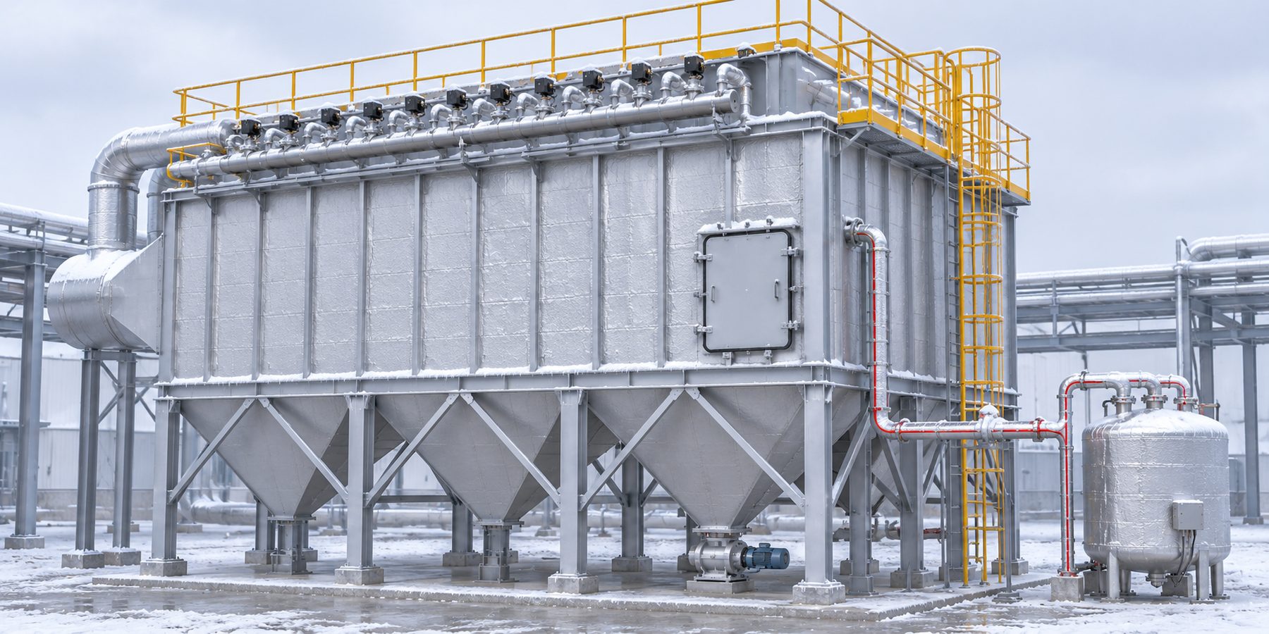 123456
The numbers mark places where condensation or freezing is likely. Concept illustration; actual shapes and dimensions differ.
Source: compiled from public sources · AI-assisted concept illustration · Not actual shape or dimensions
01 · WHY WINTER
Why Do Problems Appear in Winter When the Flue Gas Is Hot?
Condensation is set not by the flue gas temperature but by the temperature of the coldest surface. Even with hot flue gas, if walls, hoppers or the area around access doors cool below the dew point where they meet outdoor air, water vapor condenses right there. A baghouse supplier lists cold weather and overnight cooling as conditions that cause condensation.[1] The US EPA explains that the baghouse body and connecting ducts are insulated, and can be heated where condensation is possible.[2]
Winter problems show different symptoms at different locations. Table 1 shows where each symptom appears and what to check first.
| Location | Winter symptom | Check first |
|---|---|---|
| Compressed air header and tubes | Moisture freezes and blocks the line | Pressure dew point, drain discharge (Section 02) |
| Pulse valves | Valves fail to open and cleaning weakens | Whether differential pressure recovers after cleaning (Section 02) |
| Hopper | Wet dust builds up and blocks the outlet | Wall temperature, discharge device running (Section 03) |
| Access doors and walls | Cold air enters through gaps and the door area gets wet | Gasket seal, wetness around doors (Section 03) |
| Reagent line | Urea crystallizes or dilution water freezes | Tank and line temperature, circulation (Section 04) |
| Filter inlet (with catalytic filter bags) | Duct heat loss lowers the temperature | Inlet temperature trend (Section 05) |
This article covers problems caused by outdoor air during operation. Flue gas passing through the acid dew point at start-up and shutdown needs a separate check; you can estimate the acid dew point with the acid dew point calculator.
Winter Checks Fall into Five Steps
This order is compiled from public sources, and Sections 02 to 05 follow it.
- Compressed air: Check that the pressure dew point is below the lowest ambient temperature and that the drains discharge.
- Pulse valves: Check insulation and heaters, and whether differential pressure recovers after cleaning.
- Hoppers, walls and access doors: Check insulation, heaters and gasket leaks.
- Urea and dilution water lines: Check heating, circulation and insulation.
- Record baselines: Write down differential pressure and inlet temperature at the start of winter.
02 · COMPRESSED AIR
Why Does Pulse-Cleaning Compressed Air Freeze?
When moisture in compressed air that has cooled in outdoor headers and tubes freezes, the pulse valve system gets blocked. A dust collector supplier explains that this moisture turns into ice crystals that block valves and tubes and impair solenoid function.[3] If valves do not open on time, cleaning weakens, more dust builds up on the filter media, and the differential pressure rises.
The pressure dew point is the temperature at which compressed air starts to release water at its operating pressure. A Compressed Air Challenge article recommends setting the pressure dew point 20°F (about 11°C) below the lowest ambient temperature.[4] According to the same article, refrigerated dryers deliver a pressure dew point of 35°F or 50°F (about 2°C or 10°C), and regenerative desiccant dryers −40°F (−40°C) or lower (based on 100°F saturated inlet air).[4]
The pressure dew point (dashed line) must be below the lowest ambient temperature (solid line). The shaded area is where the dew point is above ambient and condensation or freezing can occur. Concept graph, not measured data. The 20°F (about 11°C) margin is the Compressed Air Challenge recommendation.[4]
Source: compiled from public sources · Concept graph · Not measured data
By this rule, a refrigerated dryer with a 35°F (about 2°C) pressure dew point meets the target only while outdoor piping stays above about 55°F (about 13°C). This is our own calculation, not a figure from the source, and in plants where outdoor sections get colder, a refrigerated dryer alone may not be enough.
Supplier materials describe the fixes. One recommends a separate drying system, automatic drains and heaters for exposed solenoid valves,[3] and another recommends checking dryers and drain valves and adding automatic purge valves or inline air filters.[1] The Compressed Air Challenge article says to confirm that condensate that should be removed ahead of the dryer is actually removed.[4] There is also a warning that wet compressed air sends water to the clean side of the filter (where filtered air leaves) with every pulse.[1]
Table 2 lists the check values and what to do when they are out of range.
| Item | Check value | If out of range | Basis |
|---|---|---|---|
| Pressure dew point | For outdoor sections, 20°F (about 11°C) below the lowest ambient | Review dryer type and capacity, and consider insulating outdoor piping | [4] |
| Drains | Condensate is actually discharged ahead of the dryer | Repair the valve or consider automatic drains | [4][3] |
| Header condensate | Water collects at low points of the outdoor header | Consider adding drain points and insulating that section | Check item in this article |
| Valve heating | Exposed solenoid valves have working heaters | Add or replace heaters | [3] |
| Differential pressure after cleaning | Returns to the value recorded at the start of winter | If it does not, check valve operation and air moisture first | [3] |
03 · COLD WALLS & HOPPER
What Happens at the Hoppers and Walls?
When cold hopper walls condense, dust sticks, builds up and forms a bridge that blocks the outlet. One supplier explains that moisture-laden dust bridges across the hopper discharge,[3] and another explains that dust stuck to wet walls blocks the outlet and backs up into the collector, increasing resistance.[1]
The countermeasures are insulation, heating and keeping the discharge device running. One supplier recommends insulating ducts, hoppers and collector walls,[1] and another recommends insulating vulnerable areas such as hoppers, heat tracing at the discharge, and running the discharge device continuously.[3] The EPA also describes insulating the body and ducts and heating them where needed.[2] Decide when to turn heaters on not by the calendar but by whether wall and gas temperatures are above the dew point.[2]
Air leaks are a winter problem too. One supplier explains that every leak lets in cold, humid outdoor air,[1] and another says to check access port gaskets and door seals.[3]
In surface filtration, dust collects on the media surface, so wet dust that hardens may not release easily during cleaning. DuraFill™ ePTFE membrane filter bags and CataFill™ catalytic filter bags are also surface filtration designs. The difference is explained in Depth Filtration vs. Surface Filtration: What Is the Difference?.
Table 3 narrows down causes from symptoms. The causes are possibilities, so confirm them with the check values.
| Symptom | Possible cause | Action |
|---|---|---|
| Poor hopper discharge | Hopper wall condensation makes wet dust stick and bridge[3][1] | Check wall temperature, upgrade insulation and heaters, keep the discharge device running |
| Rising differential pressure in one compartment only | That compartment's wall may be cold or leaking, so wet dust may have stuck | Check that compartment's wall temperature, gaskets and door seals first |
| Wet area around doors | Humid outdoor air enters through gasket gaps[1] | Repair the gaskets and door seals |
| Water marks on the clean side | Compressed air moisture enters with each pulse[1] | Check the pressure dew point and drains in Section 02 |
04 · REAGENT LINES
How Do You Protect Urea and Aqueous Ammonia Lines?
The higher its concentration, the more easily urea solution crystallizes, so the tank and lines must be insulated, heated and circulated. SNCR systems are described in the US EPA Cost Manual, which gives the crystallization temperature of 50% urea solution as 64°F (about 18°C) and explains that heating and circulation are needed in cold climates.[5] The same manual's equipment list for urea-based SNCR includes an insulated tank, heating pads, and insulated, heat-traced piping, and lists the dilution water piping the same way. It also notes that heat tracing and insulation are applied depending on site conditions.[5]
For 32.5% urea solution, OCI's AdBlue® product data sheet gives a freezing point of −11°C to −15°C.[6] This is a product specification, not an SNCR equipment specification. Because the concentration and terms (crystallization temperature, freezing point) differ, do not read it against the EPA value; take only the point that the solidifying temperature changes with concentration.
Aqueous ammonia is different. EPA Table 1.4 gives the crystallization temperature of aqueous ammonia (19.0% as supplied) as −110°F (about −79°C) and does not describe insulation requirements.[5] Water used for dilution, however, freezes below 0°C, so the dilution water line is the first item to check. This sentence is a principle based on the freezing point of water.
At sites using catalytic filter bags, ammonia is the standard reagent, and urea solution can also be used. With urea, review the injection point or a decomposition unit so that it breaks down into ammonia before reaching the filters. Follow the supplier's operating instructions for winter injection and cut-off temperatures.
| Reagent | Crystallization or freezing temperature | Countermeasures | Basis |
|---|---|---|---|
| 50% urea solution | 64°F (about 18°C) | Insulated tank and heating pads, heating and circulation, insulated heat-traced piping | [5] |
| 32.5% urea solution | −11°C to −15°C (freezing point, product specification) | Check whether storage and line temperatures fall below this value | [6] supplier material |
| Aqueous ammonia | −110°F (about −79°C), 19.0% as supplied | Check the dilution water line before the neat reagent | [5] |
| Dilution water | Freezing point of water (0°C) | Insulated, heat-traced piping (per the EPA urea-based SNCR equipment list) | [5] |
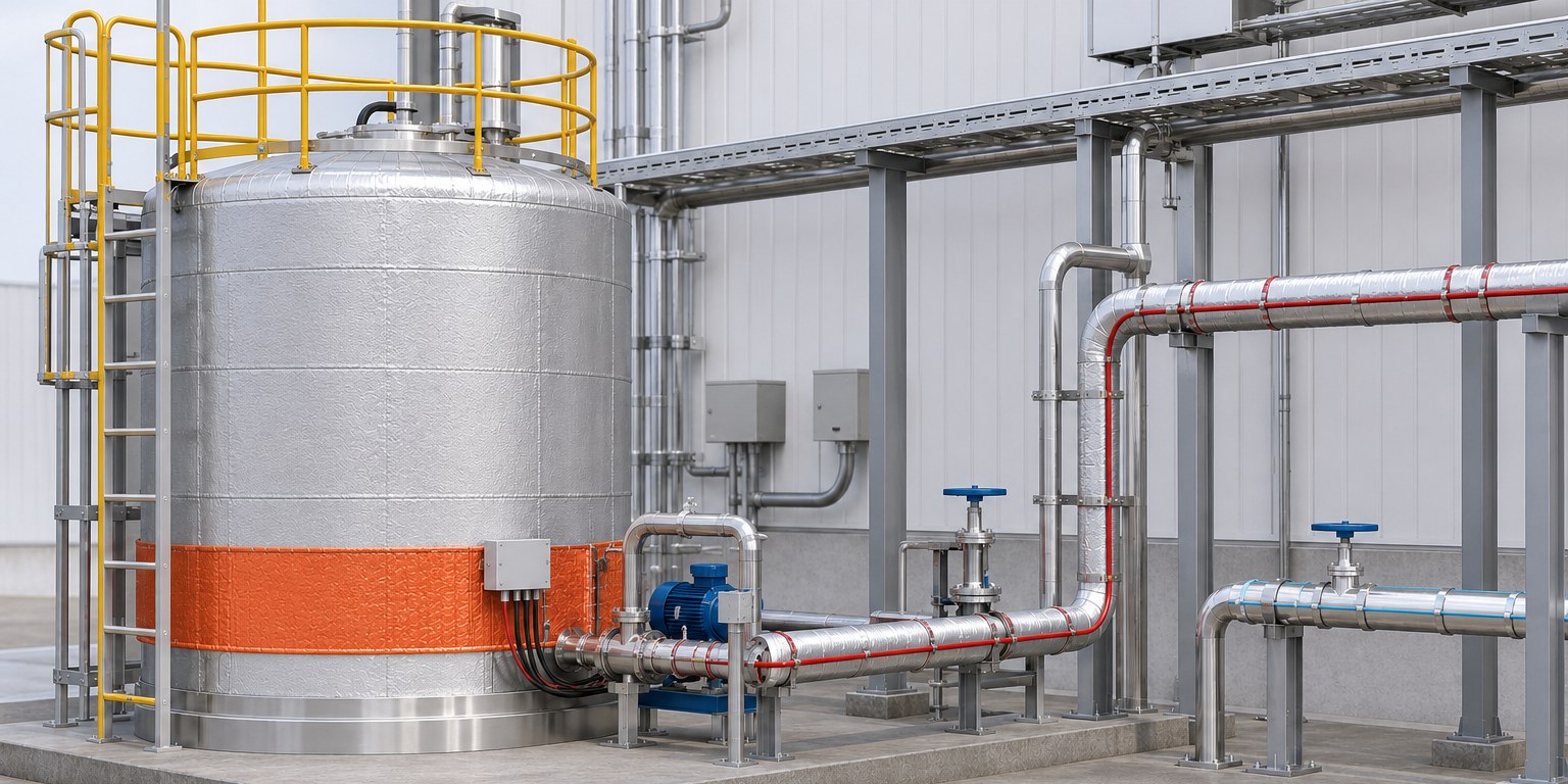 12345
Concept illustration; actual equipment layouts differ.
Source: AI-assisted concept illustration based on the equipment list in the US EPA Cost Manual · Not actual shape or dimensions
05 · CATALYTIC BAGS
What Else Changes for Catalytic Filter Bags in Winter?
Plants with catalytic filter bags have one more winter check: inlet temperature. Heat lost through the ducts can lower the filter inlet temperature. CataFill™ is used at flue gas temperatures of 120–200°C, and 180°C or above is recommended for NOx reduction. Watch the inlet temperature as a trend against these values.
There is also an example from a different design. A Danish EPA (MUDP) demonstration report, describing Topsoe's CataFlex™ catalytic filter bags, states that the filter temperature must be raised to about 185°C or higher to avoid excessive ammonium bisulfate (ABS) build-up on the catalyst (not applicable if already above that).[7] This is a case with a different design under different conditions at a power plant that mainly burns straw, and it is not converted to or compared with the CataFill™ values.
Follow the supplier's operating instructions for reagent injection and cut-off temperatures. Compare inlet temperature, differential pressure and NOx trends with values recorded at the same load before winter, and interpret NOx reduction together with the 180°C-or-above operating condition. If the inlet temperature drops below the recommended range, check duct insulation and air leaks first.[2] Check items are listed in the catalytic filter checklist.
| Check value | Target | If out of range |
|---|---|---|
| Inlet temperature | 120–200°C operating range; 180°C or above recommended for NOx reduction | Find the hours when it drops below 180°C, check duct insulation and leaks, and follow the supplier's instructions for reagent operation |
| differential pressure | Value recorded at the start of winter | If it keeps rising above the record, check compressed air and condensation in Sections 02 and 03 |
| NOx trend | Pre-winter value at the same load | Check inlet temperature and reagent supply together |
| Reagent supply | Injection and cut-off conditions in the supplier's operating instructions | Check line insulation and circulation in Section 04, then contact the supplier |
FAQ
Frequently Asked Questions
Is a refrigerated dryer enough for winter cleaning air?
Not always; it may fall short in winter when outdoor piping cools. Using the rule of a pressure dew point 20°F below the lowest ambient, a refrigerated dryer with a 35°F pressure dew point meets the target only while outdoor piping stays above about 55°F (about 13°C).[4] Check the lowest temperature of the outdoor sections together with the dryer type.
Do hopper heaters only need to run in winter?
No; decide by wall temperature rather than season. Hopper wall and gas temperatures must stay above the dew point to prevent condensation.[2] Overnight cooling and temperature swings between seasons are also listed as condensation conditions, so check wall temperature in autumn and spring as well.[1]
Can aqueous ammonia freeze too?
The dilution water line can freeze before the neat reagent does. EPA Table 1.4 gives the crystallization temperature of aqueous ammonia (19.0% as supplied) as −110°F (about −79°C).[5] Water used for dilution freezes below 0°C, so treat the dilution water line as an insulation item.
Should winter differential pressure baselines be reset?
Yes; record baseline values at the start of winter. A supplier recommends checking that differential pressure monitors read the winter baseline correctly.[3] With a record, you can tell whether a winter rise in differential pressure comes from condensation or normal variation.
- Baghouse.com, “How to Prevent Condensation in Your Baghouse,” 2026. Supplier material Link
- U.S. EPA, 「EPA-CICA Fact Sheet Fabric Filter Pulse-Jet Cleaned Type」, EPA-452/F-03-025. Link
- A.C.T. Dust Collectors, “Winterize Your Facility and Outdoor Industrial Dust Collector.” Supplier material Link
- Compressed Air Challenge(Ron Marshall), 「How's the Weather in Your Pipes?」, Compressed Air Best Practices, 2012. Link
- U.S. EPA, Air Pollution Control Cost Manual, 7th ed., “Selective Noncatalytic Reduction” chapter (Tables 1.4 and 1.5). Link
- OCI, “Urea Solution 32,5% (AdBlue®) Product Data Sheet.” Supplier material · Product specification, not an SNCR equipment specification Link
- Danish EPA (Miljøstyrelsen) MUDP, “CataFlex catalytic bags at Snetterton,” 2022. One case with another company's product under different conditions Link