

Can You Retrofit Catalytic Filter Bags Into an Existing Baghouse?
From the five checks to a one-compartment pilot
01 · WHAT CHANGES
What Changes When You Switch to Catalytic Filter Bags?
A catalytic filter bag is a filter bag with a DeNOx catalyst loaded into its fibers, so dust and nitrogen oxides (NOx) are reduced together inside the baghouse. Because NOx reduction takes place in the dust collector itself, the layout differs from installing a separate SCR reactor.
The scope of a retrofit can be split as follows.
- What stays (if dimensions fit): baghouse housing, tubesheet, cages and cleaning system
- What changes or is added: filter bags, a reagent injection system upstream of the filters, and temperature and pressure drop targets
Replacing the bags alone does not reduce NOx. The catalytic reaction only takes place when the reagent is already mixed into the flue gas before it reaches the filter. Topsoe's product page for its catalytic filter bags (manufacturer literature) likewise states that a reducing agent such as NH₃ must be present or injected upstream of the filter.[1]
Catalytic filter bag designs differ by manufacturer. Topsoe describes a catalytic fabric layer installed inside a standard filter bag.[1] Gore describes an ePTFE membrane for particulate removal combined with a PTFE-based catalytic felt.[2] CataFill™ is a catalytic filter bag made by laminating an ePTFE membrane onto a catalyst-loaded PTFE nonwoven. Because the designs differ, the figures from the public case in this article should be read as results for a different design.
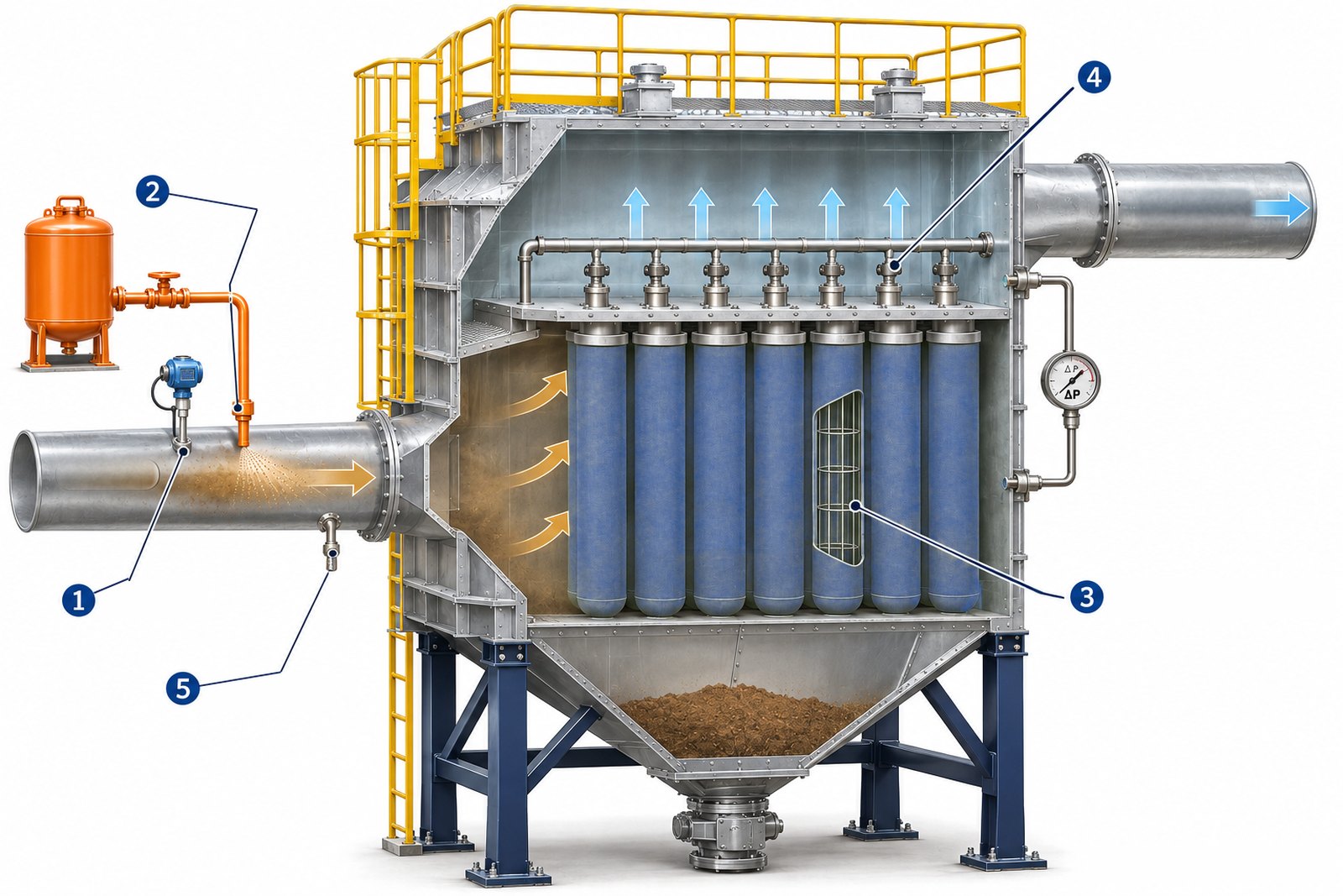
The numbers in the figure match the checks in Section 02. Flue gas enters through the duct on the left, passes through the filter bags and leaves through the duct on the right. The navy bags are catalytic filter bags; the orange tank and piping are the reagent injection system that is added.
Source: Based on Micro-one in-house technical data · AI-assisted concept illustration · Not actual shape or dimensions
02 · FIVE CHECKS
What Should You Check Before the Retrofit?
There are five things to check. The table below sets out what to look at for each item and why it matters.
| Check | What to look at | Why it matters |
|---|---|---|
| ① Operating temperature | Lowest baghouse inlet temperature during normal, low-load and start-up operation | CataFill™ is applied at flue gas temperatures of 120–200°C, and 180°C or higher is recommended for NOx reduction. At lower temperatures the reduction rate falls and ammonium bisulfate (ABS) can form. See Why Do SCR Catalysts Deactivate? Poisoning, Temperature and Ammonia Slip for details. |
| ② Reagent injection | Whether an SNCR system already exists, the injection nozzle position upstream of the baghouse and mixing distance, measures against condensate in the piping and nozzle plugging | The catalytic reaction only occurs if the reagent is mixed into the flue gas before it reaches the filter. Consumption can be estimated with the urea and ammonia consumption calculator. |
| ③ Baghouse dimensions | Tubesheet hole diameter, cage diameter, length and number of wires, bag length, air-to-cloth ratio (A/C) | The bags have to fit the tubesheet and cages, so drawings and measured dimensions are needed. Check the air-to-cloth ratio (gas flow divided by filter area) with the air-to-cloth ratio calculator. |
| ④ Pressure drop and cleaning margin | Current pressure drop trend, fan margin, whether cleaning pressure can be set per compartment | Catalytic filter bags can raise pressure drop and may need a different cleaning pressure. Section 03 covers a public case. |
| ⑤ Flue gas composition | SO₂ and SO₃, catalyst poisons such as alkali and heavy metals, moisture, and whether acid gas treatment (semi-dry or dry reactor) is installed | SO₂ and SO₃ can contribute to ABS formation, and alkali and heavy metals can degrade catalyst performance. |
When a Bag Change Alone Is Not Enough to Decide
In the five cases below, do not treat the retrofit as a simple bag change; review separately whether equipment upgrades are needed and whether the application is feasible.
- The baghouse inlet temperature falls outside the CataFill™ application range (120–200°C) at times, or stays below the temperature recommended for NOx reduction (180°C or higher) for long periods
- There is no practical location or piping route for injecting and mixing the reagent upstream of the filters
- The tubesheet or cage dimensions do not match the filter bag dimensions
- The fan and cleaning system have so little margin that even a small rise in pressure drop affects operation
- SO₂ and SO₃ levels are high with no acid gas treatment upstream of the filters, or catalyst poisons are abundant
03 · PRESSURE DROP AND LIFE
How Do Pressure Drop and Bag Life Change?
Pressure drop may rise slightly depending on site conditions, so fan and cleaning margins should be checked in advance. One public field trial is described below, with its conditions.
A 2022 report by the Danish Environmental Protection Agency (Miljøstyrelsen) covers a trial in which Topsoe CataFlex™ catalytic filter bags were installed in one compartment of the Snetterton biomass power plant in the UK.[3] The plant is a 50 MWe unit fired primarily on straw. According to the report, the compartment with catalytic filter bags had a pressure drop 2–3 mbar (200–300 Pa, about 20–30 mmH₂O) higher than a compartment with standard bags, which the report judged marginal compared with the pressure drop of the whole flue gas system.[3]
The same report explains that filters fitted with catalytic inner bags typically require a slightly higher cleaning pressure. That baghouse, however, could not adjust cleaning pressure per compartment, so the trial compartment could not be given a higher pressure.[3]
No. The case above shows how a different design, with a catalytic bag inserted inside an outer filter bag, performed at one site. Operating conditions also differ, so the figures should not be carried over to CataFill™ pressure drop or cleaning conditions.
The CataFill™ pressure drop can be checked against the range of Korea's Environmental New Technology (NET) certification No. 631 (100 mmH₂O or less). Pressure drop at an individual site depends on operating conditions.
CataFill™ Is Typically Replaced About Every Two Years
For reference, the US EPA cost manual states that, for coal-fired boiler applications, SCR catalyst vendors typically guarantee an operating life of 8,000 to 24,000 hours.[4] Two years of continuous operation is about 17,500 hours, so the CataFill™ replacement interval falls within that guarantee range.
The same document also notes that actual catalyst layer lifetimes in coal-fired SCR are often 5 to 7 years.[4] Those values come from equipment with different operating temperatures and designs, so they should not be read as meaning SCR catalyst lasts two years. The CataFill™ replacement interval also varies with operating temperature, catalyst poisons and cleaning conditions.
04 · FIELD LESSONS
Where Can a Retrofit Run Into Trouble on Site?
The Danish report discussed above is also a case in which the on-site DeNOx test could not be completed.[3] Here the problem appeared first in the system feeding the reagent, ammonia, rather than in the catalyst.
The report describes the sequence as follows. First, the injection line was under vacuum, so condensate could not drain and the line plugged. Next, injection nozzles on the dust side of the filter fouled. After that there was no longer enough overpressure to push the ammonia in, which the report says was probably due to a slightly increased pressure drop over the filter. In the end, time and budget ran out and this part of the test was abandoned.[3]
The same report took samples from catalytic filter bags after 6, 14 and 22 months in service, tested their activity in the laboratory, and found that they had not deactivated significantly.[3] This was a laboratory test, not an on-site DeNOx test, and it is one case for one Topsoe product.
On temperature, the report states that with this type of product the filter temperature usually has to be raised to about 185°C or more (if it is not already) to avoid excessive ABS fouling. The plant's normal filter temperature was 200–210°C.[3] CataFill™ operation is assessed separately against its application range of 120–200°C, with 180°C or higher recommended for NOx reduction.
Check Points From the Public Case
- Injection piping: confirm at the design stage where condensate collects and how it is drained
- Injection nozzles: inspection and cleaning of nozzles located on the dust side
- Injection pressure: enough pressure margin to push the reagent in even after filter pressure drop rises
- Test plan: a test period and measurement plan that include time to fix the injection system
These check points are drawn from a single public case and do not mean the same problems will occur at every site.
05 · PILOT FIRST
What Is a Safe Sequence for Introducing Catalytic Filter Bags?
If the baghouse is divided into compartments, one option is to fit a single compartment first. The sequence can be summed up in four steps.
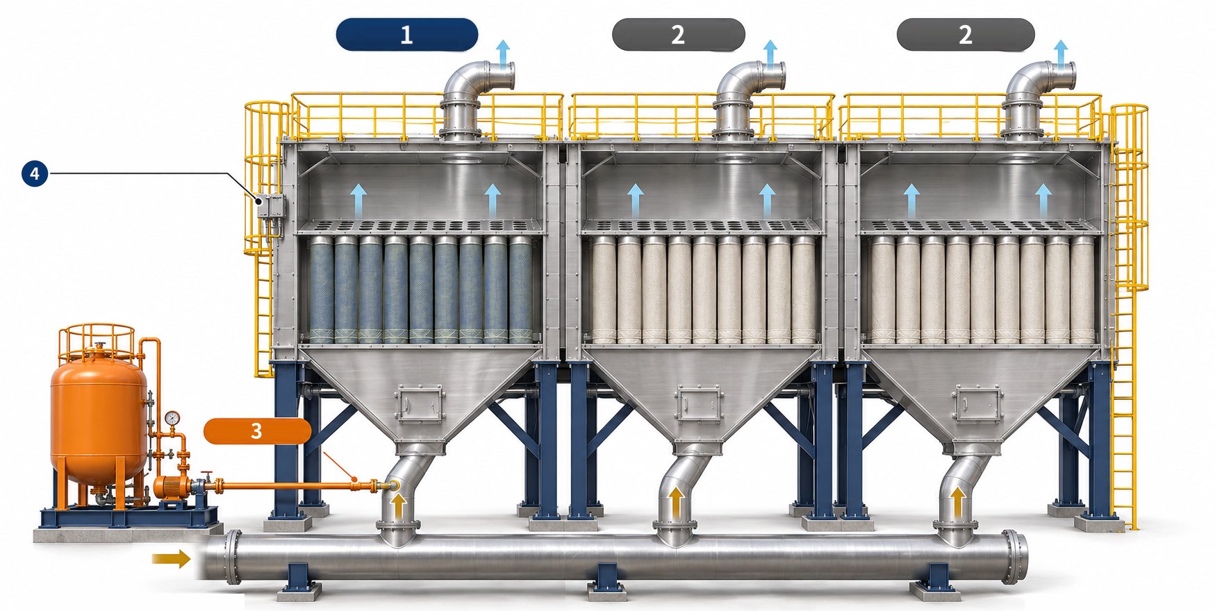
Legend: orange arrows show flue gas coming in; light-blue arrows show treated gas leaving. Each compartment has its own inlet and outlet.
Source: Based on Micro-one in-house technical data · AI-assisted concept illustration · Not actual shape or dimensions
The public case above also fitted only one compartment of 196 bags first, out of 1,568 bags in total.[3] The table below shows what to look at in each step and what to decide from the results. Ammonia slip is ammonia that leaves through the stack without reacting.
| Step | What to measure, and how | Who checks | What the result decides |
|---|---|---|---|
| 1. Review operating data | The five items in Section 02: flue gas flow and temperature (minimum, average, maximum), inlet and target NOx concentrations, baghouse drawings | Plant operator, filter bag supplier | If conditions fit, choose the pilot compartment; if not, consider equipment upgrades or putting the application on hold |
| 2. Pilot in one compartment | Catalytic filter bags and reagent injection applied to one compartment only; whether compartments can be operated separately | Plant operator, filter bag supplier | If compartments cannot be separated, review a different pilot approach |
| 3. Measure pressure drop, NOx and slip | Compare pressure drop, NOx and ammonia slip at the pilot compartment outlet and an existing compartment outlet (at the stack the gas is mixed with other compartments and diluted). Measure baseline values at the same points before the retrofit | Plant operator (in-house or third-party measurement) | If within the target range, consider extending; if not, adjust injection or cleaning conditions and measure again, or run further tests |
| 4. Extend to all compartments | Pilot results and the bag replacement schedule for the remaining compartments | Plant operator | Decide when and in what order to extend |
The target range in the table is not a value set by Micro-one; it is agreed site by site between the plant operator and the filter bag supplier.
06 · CHECKLIST
What Data Do You Need When Requesting a Review?
With the data below, operating temperature and reagent injection conditions can be reviewed in detail.
- Flue gas flow and temperature (minimum, average, maximum)
- Inlet and target NOx concentrations
- SO₂, HCl and moisture, plus SO₃ if measured
- Dust concentration and composition (alkali, heavy metals, etc.)
- Baghouse drawings (tubesheet and cages)
- Current filter bag specifications
- Pressure drop trend and fan margin
- Cleaning method and pressure (whether adjustable per compartment)
- Whether SNCR or sorbent injection is installed
Items to check during operation after the retrofit are listed separately in the catalytic filter bag operating checklist.
FAQ
Frequently Asked Questions
Can catalytic filter bags be trialed in only some compartments first?
Yes. If the baghouse can be operated compartment by compartment, one option is to fit one compartment first and compare its pressure drop and NOx with the other compartments. The public case described above also fitted one compartment of 196 bags first, out of 1,568.[3]
Can the existing SNCR reagent equipment be shared?
Some of it can. Reuse of the storage tank, supply pumps and dilution water equipment can be considered when their spare capacity covers the consumption at the new injection point (combined consumption if SNCR keeps running), when they can deliver the required pressure and flow at the new nozzles upstream of the baghouse, and when the reagent type and piping route suit the new injection method. However, SNCR injection points are set for the optimum urea reaction window (about 900–1,150°C),[5] so new nozzles and a mixing section are needed upstream of a baghouse running at 120–200°C. If urea is used, it may not decompose sufficiently in 120–200°C flue gas before reaching the filter, so a separate decomposition unit or ammonia water should be considered; the US EPA cost manual also notes that for SCR, urea is generally converted to ammonia before injection.[4]
Does cleaning pressure also need adjusting after switching to catalytic filter bags?
It may. The public case report explains that filters fitted with catalytic bags typically require a slightly higher cleaning pressure.[3] Check in advance whether cleaning pressure can be set per compartment, and follow the supplier's operating instructions for CataFill™ cleaning conditions.
What operating data is needed to request a review?
You will need flue gas flow and temperature (minimum, average, maximum), inlet and target NOx concentrations, SO₂, SO₃, HCl and moisture, dust concentration and composition, baghouse drawings (tubesheet and cages), current filter bag specifications, pressure drop trend and fan and cleaning margins, and whether SNCR or sorbent injection is installed. See Section 06 for each item.
- Topsoe, "CataFlex™ catalytic filter bags," product page (manufacturer literature). Link
- W. L. Gore & Associates, "GORE® DeNOx Catalytic Filter Bags," product page (manufacturer literature). Link
- Danish Environmental Protection Agency (Miljøstyrelsen), "Advanced catalytic bags for combined abatement of NOx and particulate matter in biomass boilers," 2022 (field trial of Topsoe CataFlex™; one case with a different design and conditions). Link
- US EPA, "Air Pollution Control Cost Manual, Section 4, Chapter 2: Selective Catalytic Reduction," 2016 (revised 2017). Link
- US EPA, "Air Pollution Control Cost Manual, Section 4, Chapter 1: Selective Noncatalytic Reduction," 2016 (revised 2017). Link