

How Do Catalytic Filters Remove Dust and NOx Together?
From definition and working principle to a comparison of ceramic and fiber-type designs, application conditions and a review checklist
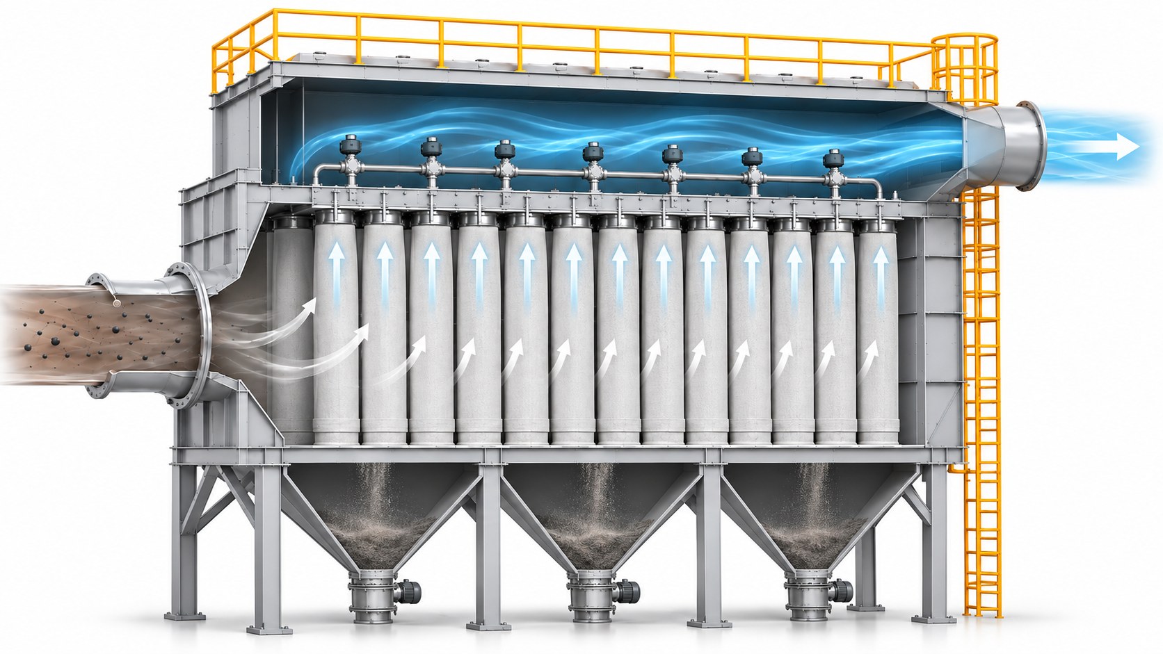 Dust + NOx
InClean Gas
OutCaptured Dust Out
Figure 1. Concept illustration of flue gas passing through the filter bags in a baghouse while captured dust falls into the hopper. The structure inside the filter bag wall is explained in Figure 2 below. Dimensions and shapes differ from actual equipment.
Source: Based on Micro-one in-house technical data · AI-assisted concept illustration
01 · DEFINITION
What is a catalytic filter, and how does it treat dust and NOx together?
A catalytic filter performs filtration and DeNOx in a single filter. Instead of handing dust capture and NOx reduction to separate pieces of equipment, it carries them out in sequence within the filter structure. The concept is known as catalytic filtration, and it is not new.
A catalyst takes part in a reaction without being consumed, lowering the energy the reaction needs (the activation energy). As a result, the reaction proceeds at lower temperatures than it would without a catalyst. The same principle is used in automotive exhaust treatment, petroleum refining and NOx reduction at power plants and incinerators. The main reaction in DeNOx is 4NO + 4NH₃ + O₂ → 4N₂ + 6H₂O.
The sequence is surface filtration, reagent mixing, then catalytic reaction
The order matters. Capturing dust first limits how much dust reaches the catalyst layer directly, which generally helps reduce erosion of the catalyst and plugging of its pores (tiny openings). This sets it apart from configurations that expose the catalyst directly to dust-laden flue gas.
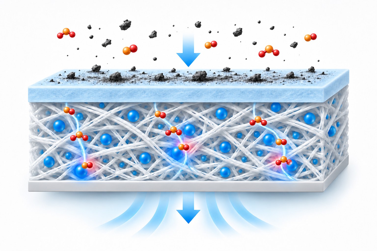 Dust + NOx InePTFE MembraneClean Gas Out
- ePTFE membrane: the flat filtration layer at the front (light-blue layer) that stops dust at the surface
- Catalyst-loaded PTFE nonwoven: the layer where NOx reacts, with catalyst particles embedded between the fibers
Figure 2. Concept illustration of a filter cross-section, in which dust stops at the membrane surface and NOx reacts in the catalyst-loaded nonwoven. Membrane thickness and particle size are exaggerated for clarity and differ from actual dimensions.
Source: Based on Micro-one in-house technical data · AI-assisted concept illustration
The filter is designed so that a filtration layer sits in front of the catalyst layer, which limits how much dust reaches the catalyst directly. Filtration, however, works by capturing particles, so gaseous components pass through. This is covered under conditions and limits below.
02 · TECHNOLOGY FLOW
How did catalytic filter technology move from ceramic candles to fiber-type filters?
The first approach was to add catalyst to ceramic candle filters. Fiber-type filters, with catalyst loaded onto flexible filter media, came later and opened a path to bringing catalytic filtration into an existing baghouse simply by replacing its filter bags.
Ceramic candles: catalyst in a rigid filter wall
A catalytic ceramic candle puts catalyst into the wall of a cylindrical filter (the candle) made of ceramic fiber, so a single element captures dust and reduces NOx. Tri-Mer's UltraCat (USA) is a lightweight fibrous ceramic filter with catalyst particles embedded throughout the filter wall,[1] and Clear Edge's Cerafil TopKat (UK) is a catalytic ceramic filter element developed jointly with Haldor Topsøe.[3] As an example of dimensions, Tri-Mer literature describes filters 10 ft (about 3 m) long and 6 in. (about 150 mm) in diameter, cleaned by reverse pulse.[2] In the same manufacturer's literature, NOx control begins at about 350°F (about 177°C).[1]
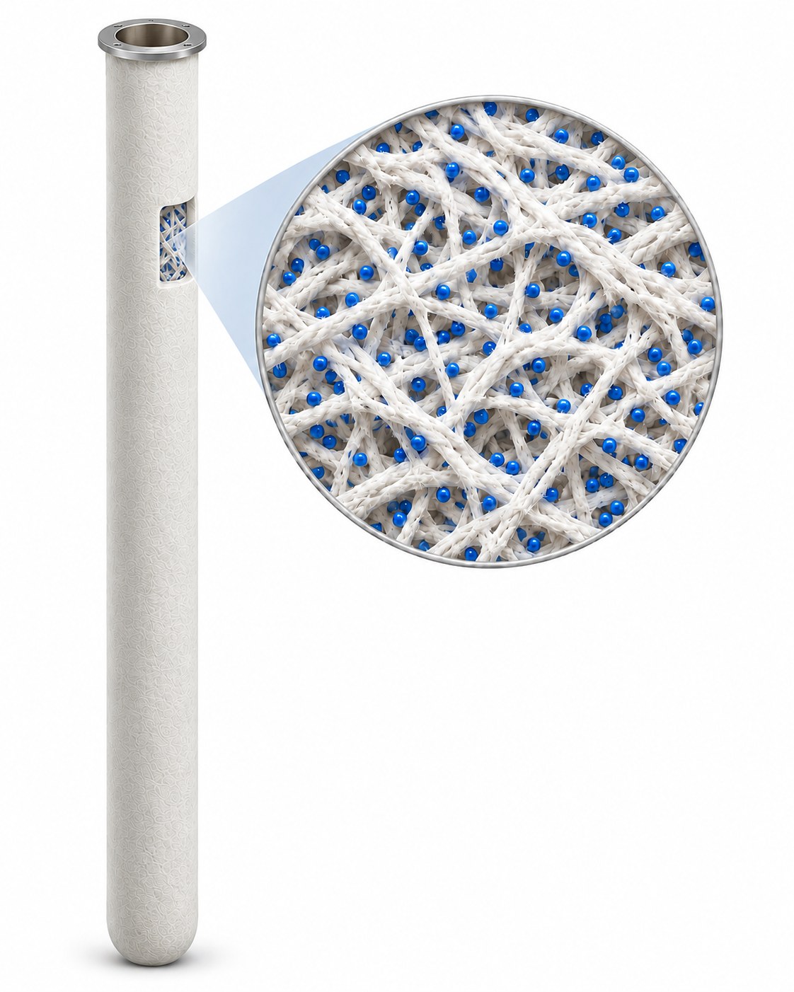 Ceramic CandleCeramic Fibers with
Embedded Catalyst
Figure 3. Concept illustration of a catalytic ceramic candle. Catalyst particles (blue) are embedded in the wall of a long, slender cylindrical filter made of ceramic fiber. Fiber thickness and particle size in the magnified view are drawn for clarity.
Source: Based on Micro-one in-house technical data · AI-assisted concept illustration
What to check when considering ceramic candles
- Length limit: Catalytic ceramic candles are typically 2 m long, and at most about 3 m. Patent literature explains that the mechanical properties of sintered ceramic and the mechanical stresses during operation make longer candles difficult to produce, which limits the filtration area of each candle.[4]
- Filtration area: By simple calculation, the cylindrical surface of a candle 3 m long and 150 mm in diameter is about 1.4 m², while a filter bag 6 m long and 160 mm in diameter is about 3.0 m². Switching to candles in a large baghouse that uses 6–8 m long bags can cut filtration area considerably, so gas flow rate and air-to-cloth ratio must be recalculated. These values cover the outer cylindrical surface only; actual filtration area depends on product design.
- Breakage control: Because of the nature of ceramic materials, the risk of breakage from impact during shipping, installation and cleaning has to be managed. That said, Tri-Mer describes its filters as lightweight, ductile ceramic filters,[1] so specifications and handling conditions should be checked product by product.
Fiber-type: catalyst loaded onto filter bag media
A fiber-type catalytic filter carries catalyst on flexible filter media of the kind used in filter bags. Its commercialization created a way to add catalytic filtration to an existing baghouse by replacing only the filter bags. Topsoe's CataFlex™ places a catalytic fabric layer inside a standard filter bag,[5] while Gore's GORE® DeNOx combines an ePTFE membrane with a PTFE-based catalytic felt.[6] Construction differs from one manufacturer to another.
Catalytic filter bag suppliers with bags installed and operating at customer plants are few, including Gore, Topsoe and Micro-one.
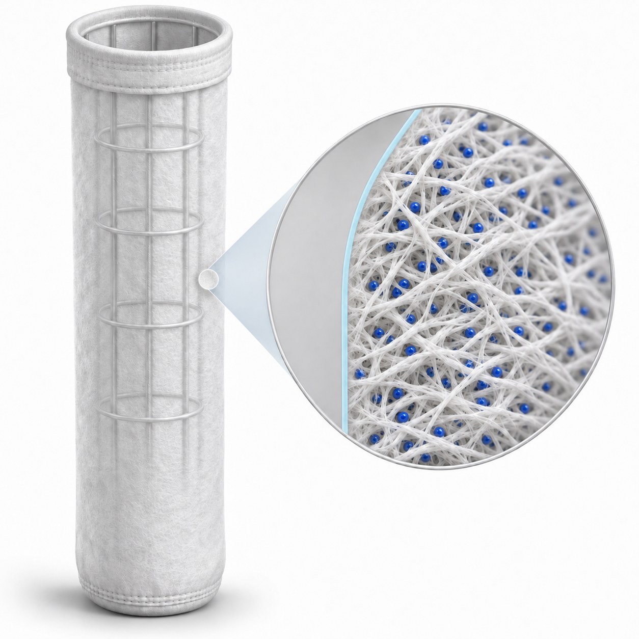 Filter BagePTFE
MembraneCatalyst-Loaded PTFE Nonwoven
Figure 4. Concept illustration of a fiber-type catalytic filter bag. Behind the thin, flat ePTFE membrane layer on the outside (light blue line), catalyst particles (blue) are embedded between white PTFE nonwoven fibers. Layer colors and thickness, and particle size and spacing, are drawn for clarity.
Source: Based on Micro-one in-house technical data · AI-assisted concept illustration
Why membrane pore size must be uniform
In its construction of an ePTFE membrane laminated onto a catalyst-loaded PTFE nonwoven, Micro-one treats uniform membrane pore size as a design criterion. Non-uniform pores can, first, raise pressure drop and fan power cost; second, channel gas toward low-resistance spots (uneven permeation) and lower DeNOx efficiency; and third, concentrate stress at one point during repeated cleaning and rupture the membrane. How a membrane captures dust at the surface is explained in Depth Filtration vs. Surface Filtration: What Is the Difference?.
03 · COMPARISON
How do the three ways of treating dust and NOx together differ?
The biggest difference among the three is where the catalyst layer sits relative to the filter. In ceramic candles and fiber-type filters, the filter itself carries the catalyst; a catalyst module above the baghouse places the catalyst separately, downstream of the filters. The full range of incinerator NOx reduction options, including SNCR, SCR and ozone oxidation, is compared in What Are the Options When Incinerator NOx Limits Get Stricter?.
A catalyst module above the baghouse forms a low-temperature SCR by installing extruded or formed catalyst modules in the clean gas space at the top of the baghouse. Because dust is removed before the gas passes through the catalyst, catalyst erosion and particulate poisoning can be reduced, and the need for a large SCR tower and long ductwork can be reduced as well. The trade-off is access: because the catalyst modules sit directly above the filter bags, they have to be lifted out before a bag can be replaced, so a torn bag cannot be changed quickly and emergency response can be delayed.
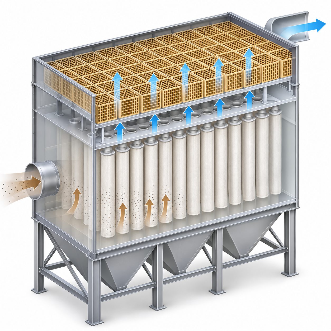 Catalyst ModuleFilter BagsHopper
Figure 5. Concept illustration of a catalyst module above the baghouse. Gas from which the filter bags have already removed dust is denitrified as it passes through the catalyst modules (yellow honeycomb) in the clean gas space above. Actual configurations vary by site.
Source: Based on Micro-one in-house technical data · AI-assisted concept illustration
| Item | Ceramic candle | Catalyst module above the baghouse | Fiber-type catalytic filter (filter bag) |
|---|---|---|---|
| Catalyst location | Inside the ceramic fiber filter wall | Separate module in the clean gas space downstream of the filters | Inside the filter bag (catalyst-loaded filter media) |
| Filtration and DeNOx | Simultaneous, in one element | Filtration in the filters, then DeNOx in the module (sequential) | Simultaneous, in one element (the filter bag) |
| Form and size | Cylindrical candle, typically 2 m long, at most about 3 m | Extruded or formed catalyst module | Same form as a conventional filter bag |
| Use in existing equipment | Can be fitted in pulse-jet collectors[1][3] (configuration must suit candle dimensions) | Requires space for the module in the clean gas space | If tubesheet and cage dimensions and operating conditions match, applied by replacing filter bags and adding a reagent injection system |
| Filter bag holes or damage | Candle breakage must be managed | Dust escaping through a hole can reach the shared downstream catalyst layer, so early detection and response matter | Each filter bag has its own catalyst layer, so the DeNOx impact is limited to that bag; handled by leak checks and replacement |
| Replacement and maintenance | Replaced candle by candle | The catalyst modules sit over the filter bags, so they must be moved or removed before any bag can be replaced. Even a single torn bag cannot be changed out quickly, which delays emergency response and lengthens maintenance outages | Standard filter bag replacement procedure |
| Pressure drop | Pressure drop of the filter itself | Filter pressure drop + catalyst module pressure drop (check by design) | Pressure drop of the catalyst-loaded filter bag (may be higher than a conventional bag; check by product) |
The table summarizes the structural features of each method; it does not mean one is better than another. The choice depends on temperature, plant size and the existing equipment layout.
Their conditions differ, so a simple comparison is not possible. In general, ceramic candles are considered for hot flue gas, and fiber-type filters for the temperature range in which existing baghouse filter bags are replaced (around 120–200°C). Either way, flue gas temperature and existing equipment dimensions must be checked first.
04 · CONDITIONS AND LIMITS
Under what conditions can catalytic filters be used, and what are their limits?
Catalytic filters can be used when three conditions are met: reagent injection, a temperature at which the catalyst is active, and compatibility with existing equipment. They are not a full replacement for a separate reactor-type SCR.
① Reagent injection is required
A catalytic filter does not break down NOx on its own. A reagent such as ammonia (NH₃) or urea solution, supplied upstream of the filter, must react with NOx on the catalyst. Topsoe states that reducing NOx requires injecting a reagent such as NH₃ upstream of the filter,[5] and Gore likewise states that its filter bags need NH₃ present to react with NOx.[7] When urea is used, the injection location or a decomposition unit is reviewed so that the urea decomposes to NH₃ before it reaches the filter. Separate reagent storage, injection and control equipment is needed, and with high dosing, ammonia slip (the release of unreacted NH₃) must be managed.
② The temperature must be right
Conventional V₂O₅-WO₃/TiO₂ SCR catalysts usually reach their design efficiency at around 300°C or higher, and even low-temperature SCR catalysts placed at the back end of an incinerator generally operate at 200°C or higher. Baghouses, by contrast, typically operate at 120–180°C. Micro-one regards this temperature gap as a challenge shared across the industry. There are two ways to close it: reheat the flue gas, or make the catalyst work at lower temperatures.
Low temperatures also carry risk. A CataFlex demonstration report published by the Danish Environmental Protection Agency states that the filter temperature should be kept at about 185°C or higher to avoid deposition of ammonium bisulphate.[8] Ammonium salts formed when NH₃ reacts with SO₃ can plug both the filter and the catalyst. For this reason, check not only the normal operating temperature but also the range of temperature swings and the startup and shutdown periods.
③ Distinguish poisoning that filtration can prevent from poisoning it cannot
Manufacturer literature also explains that filtering out dust first reduces the catalyst's exposure to components carried in the dust.[9] Gaseous substances, however, are not removed by filtration. How catalyst poisoning and ammonia slip work is explained in Why Do SCR Catalysts Deactivate? Poisoning, Temperature and Ammonia Slip.
| Component | Effect of upstream filtration | Reason |
|---|---|---|
| Fly ash and fine dust | Can be reduced | They are particles, so they are captured on the filter surface |
| Alkali components on dust (K, Na, Ca) | Can be reduced | They are filtered out along with the dust |
| Particulate heavy metals | Can be reduced | They are particles, so they are captured |
| Unreacted sorbent powder | Can be reduced | It is a powder, so it is captured. This limits calcium compounds coating the catalyst surface and reducing its activity |
| Gaseous SO₂, SO₃ and HCl | Cannot be reduced | They are gases, so filtration does not remove them |
| Water vapor (a cause of reversible activity loss) | Cannot be reduced | It is a gas, so filtration does not remove it |
| Gaseous mercury and some other volatile heavy metals | Cannot be reduced | They pass through the filter as gases |
| Ammonium salts formed by NH₃ reacting with SO₃ or HCl | Cannot be reduced (may deposit) | They are reaction products, so upstream filtration cannot stop them |
④ It is not a full replacement for a separate reactor-type SCR
If the tubesheet and cage dimensions and operating conditions of an existing baghouse meet the requirements, DeNOx capability can be added by replacing the filter bags and adding a reagent injection system. First, however, it must be assessed whether dust collection performance is maintained and whether the bags are mechanically, thermally and aerodynamically compatible with the existing equipment. Catalytic filters are one of the options considered at plants where SNCR alone struggles to meet the limit but building a new, separate SCR reactor is a heavy burden.[8] Depending on the required reduction and plant conditions, many sites are better served by a reactor-type SCR.
05 · CHECKLIST
In what order should a catalytic filter be evaluated?
The usual order is flue gas temperature, existing baghouse dimensions, reagent system, flue gas composition, required reduction, and post-startup monitoring. If an earlier step does not fit, there is no need to evaluate the later ones.
- Flue gas temperature: Check the normal operating temperature, the range of swings, and the startup and shutdown periods. Confirm that the temperature falls between the catalyst activity temperature and the heat resistance limit of the filter bags.
- Existing baghouse dimensions: Check tubesheet and cage dimensions, air-to-cloth ratio and current pressure drop margin.
- Reagent system: Decide on the injection location for NH₃ (or urea solution and how it is decomposed), mixing with the flue gas, dosing control and ammonia slip management. If SNCR is in operation, account for residual NH₃ as well.
- Flue gas composition: Check SO₂, SO₃, HCl, moisture and alkali-bearing dust. Review the upstream acid gas treatment configuration (semi-dry or dry reactor) as well.
- Required reduction: Compare current NOx emissions with the target, and judge whether the required reduction is within the range a catalytic filter can handle.
- Post-startup monitoring: Regularly check pressure drop trends, outlet NOx and NH₃ concentrations, filter bag leak checks and replacement history, and reagent consumption.
This order is a typical review flow and may vary with site conditions. Whether the technology actually fits should be decided by a preliminary review based on the site's flue gas conditions.
FAQ
Frequently asked questions
Can a catalytic filter completely replace SCR?
No. A catalytic filter reduces dust and NOx together inside an existing baghouse, and it is not a full replacement for a separate reactor-type SCR. If the required reduction is high, or if flue gas temperature or composition does not fit, a reactor-type SCR may be the better choice. Compatibility with the existing equipment must be assessed first.
Does a catalytic filter also need a reagent injection system?
Yes. In a catalytic filter, a reagent such as ammonia (NH₃) injected upstream of the filter reacts with NOx on the catalyst. If urea solution is used, it must decompose to NH₃ before it reaches the filter. Separate reagent storage, injection and control equipment is needed, and ammonia slip, the release of unreacted NH₃, must be managed as well.
Should I choose ceramic candles or a fiber-type catalytic filter?
The choice depends on flue gas temperature and the existing equipment layout. Ceramic candles need a collector configured for candle dimensions (typically 2 m long, at most about 3 m), while fiber-type filters need the tubesheet and cage dimensions and operating temperature of the existing baghouse to match. Both require a preliminary review based on the site's flue gas conditions.
Does a hole in a filter bag also affect DeNOx performance?
Yes, but the extent depends on the method. Where a shared catalyst layer sits downstream of the filters, dust escaping through a hole can reach that catalyst layer, so early detection matters. With fiber-type filters, where each filter bag carries its own catalyst, the DeNOx impact is limited to that bag and is handled by leak checks and replacement. With either method, dust escapes through a holed filter bag, so it should be found and replaced quickly.
- Tri-Mer Corporation, "UltraCat Catalyst Filters Control PM, SO2, HCl, NOx & Dioxins" (manufacturer literature, copy hosted by Georgia EPD). Tri-Mer UltraCat bulletin
- Tri-Mer Corporation, "UltraCat Ceramic Brochure" (manufacturer literature). Tri-Mer UltraCat brochure
- Andrew Startin, Clear Edge UK Ltd. Cerafil Division, "Ceramic filter elements for emission control and NOx reduction at high temperatures", 2008 (copy hosted by Georgia EPD). Clear Edge Cerafil paper
- Pall Corporation, "Catalytic filter module and catalytic filter system comprising same", US 2014/0050626 A1, 2014 (patent application). US 2014/0050626 A1
- Topsoe, "CataFlex™ catalytic filter bags" (manufacturer literature). Topsoe CataFlex
- W. L. Gore & Associates, "NOx and NH3 Filter Bags" (manufacturer literature). Gore NOx and NH3 filter bags
- W. L. Gore & Associates, "Filter Bags for the Waste-to-Energy Industry" (manufacturer literature). Gore waste-to-energy filter bags
- Danish Environmental Protection Agency (Miljøstyrelsen, MUDP), "Advanced catalytic bags for combined abatement of NOx and particulate matter in biomass boilers", 2022. Danish EPA report
- Topsoe, "CataFlex catalytic filter bags", International Cement Review, October 2020 (manufacturer article). Topsoe CataFlex in ICR