

What Are the Options When Incinerator NOx Limits Get Stricter?
Starting from existing DeNOx equipment: the conditions and limits of each option, and the order in which to choose
01 · REGULATORY PRESSURE
What changes for a plant in Korea when emission limits get stricter?
More than the concentration limit changes. For incinerators in Korea, four pressures act through separate channels: concentration, total load, charges and permits.
- Concentration: These are the permissible emission standards in the Enforcement Rule of the Clean Air Conservation Act, Annex 8. Values differ by the type, capacity and installation date of the incineration facility, so the current limit for a given facility should be checked directly in Annex 8. In the amendment effective January 2020, NOx limits were tightened by about 28% on average across all emission facilities (the degree of tightening varies by facility).[1]
- Total load: Under the Special Act on the Improvement of Air Quality in Air Control Zones, sites within an air control zone that emit NOx, SOx or dust above a certain scale (Class 1–3 sites) are allocated an emission cap separate from the concentration limits.[2] Even when the concentration limit is met, the cap can become the binding constraint first if operating hours or throughput increase.
- Charges: NOx has been subject to emission charges since 2020. Even within the permissible limit, emissions above a certain concentration incur a basic charge based on the amount emitted, and exceeding the limit incurs an excess charge. However, total-load management sites that have been allocated a NOx cap are exempt from the NOx basic charge, and instead pay a cap-exceedance penalty if they exceed the cap.[11] For this reason, keeping a margin is often more cost-effective than barely meeting the limit.
- Permits: For sites subject to an integrated environmental permit under the Act on the Integrated Control of Pollutant-Discharging Facilities, limits for each emission facility are written into the permit conditions.[3] Permit conditions and permitted emission limits are reviewed periodically, and again whenever the facility is modified.
On top of this comes stack TMS (tele-monitoring system) management. A TMS 30-minute average is the mean of six consecutive 5-minute values,[4] so even when the average concentration is within the limit, short spikes can push a 30-minute average up. The goal is twofold: lower the average and reduce fluctuation.
No. At some sites, simply reviewing the operating conditions of the existing DeNOx equipment creates headroom. Before choosing equipment, the first step is to confirm whether the current equipment is delivering its design performance.
02 · EXISTING EQUIPMENT
What should be checked before looking at the options?
The first thing to check is whether DeNOx equipment is already installed. The same tightening calls for different measures at sites with and without it.
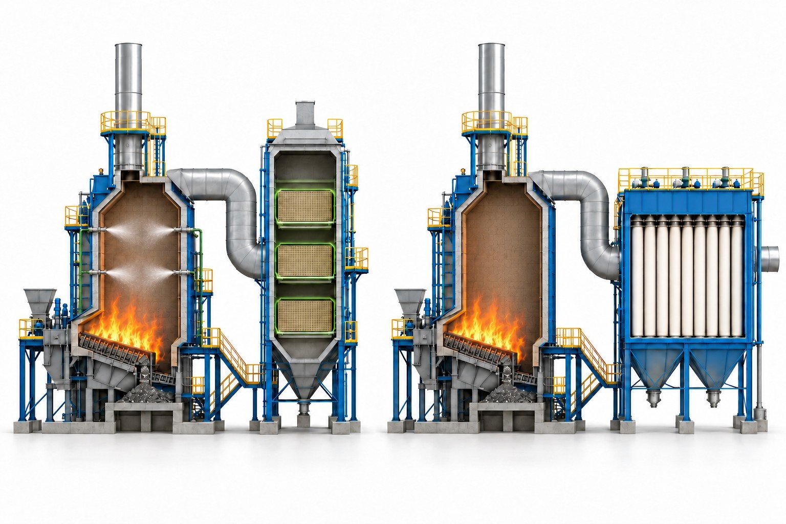
Figure 1. An incinerator with existing SNCR and SCR (left) compared with one that has only a baghouse and no DeNOx equipment (right) (concept illustration)
Left: a plant with in-furnace injection (SNCR) and a catalytic reactor (SCR). Right: a plant with only a baghouse and no DeNOx equipment.
Source: Based on Micro-one in-house technical data · AI-assisted concept illustration · actual shapes and dimensions differ
With existing equipment, the task is to supplement it
If SNCR or SCR is already installed, the first candidates are measures that close the shortfall rather than a switch to new equipment. What needs checking is why the existing equipment has reached its limit. The right supplement depends on whether the problem lies in the reagent injection location and rate, a temperature mismatch or catalyst deactivation.
Without equipment, a new-build alternative is needed
An incinerator without DeNOx equipment has to choose a method from scratch. Rather than looking at efficiency alone, first map out which equipment sits in the current flue gas train and in what order. The system layout is covered in How Is an Incinerator Flue Gas Treatment System Arranged?. In trains with little space or a low flue gas temperature, the options narrow sharply.
03 · OPTIONS
What are the options, and what are the conditions and limits of each?
NOx reduction options for incinerators fall broadly into eight types. The table below compares the conditions each method requires and the limits it runs into. Efficiency figures vary widely with site conditions, so they are left out of the table.
| Option | Requirements | Main limits |
|---|---|---|
| SNCR upgrade | An existing SNCR, with injection points that can be placed within the in-furnace temperature window | Efficiency drops outside the temperature window, and more reagent means more ammonia slip. |
| High-dust SCR (upstream) | Space and pressure-drop margin for a reactor in the hot gas before dust collection | The catalyst is directly exposed to dust and toxic components, so poisoning and erosion must be managed. |
| Tail-end SCR (low-dust) | Space for a reactor after dust collection and acid gas treatment | The gas is cool, so reheating is often needed, and reheating energy drives operating cost. |
| Catalytic ceramic candle filter | Room for new filtration equipment that treats dust and NOx together in hot gas | It assumes high-temperature operation at roughly 230–370°C, so rather than reusing an existing baghouse in the cooler section, new filtration equipment is often installed at a hot location, and investment can be large.[12] |
| Catalyst module above the baghouse | There is structural room to mount a module in the space above the baghouse | Load, gas flow and reagent mixing distance must be confirmed by design, and pressure drop may rise. |
| Fiber-type catalytic filter (catalytic filter bag) | A baghouse in service, with matching tubesheet and cage dimensions and operating temperature | A reagent injection system must be added, and NOx reduction falls at lower temperatures. |
| SNCR optimization + downstream polishing | Room to improve SNCR operation, with only a shortfall left to cover | Reagent consumption and slip of both systems must be managed together. |
| Ozone oxidation + wet scrubbing | Flue gas below 100°C, with a scrubber configured to absorb the NO₂ and N₂O₅ formed | Power for ozone generation and treatment of scrubber wastewater become operating cost items. |
Four representative methods from the table are summarized below with illustrations. The cards show at a glance where each method reduces NOx and what it requires.
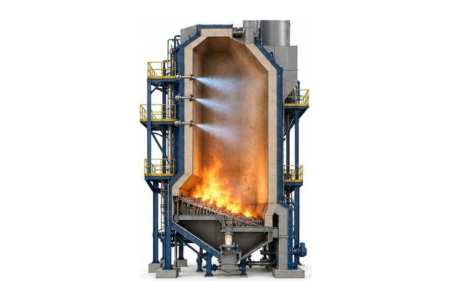
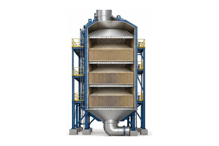
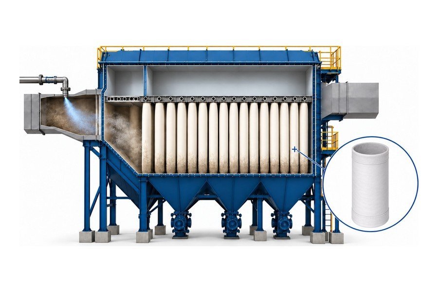
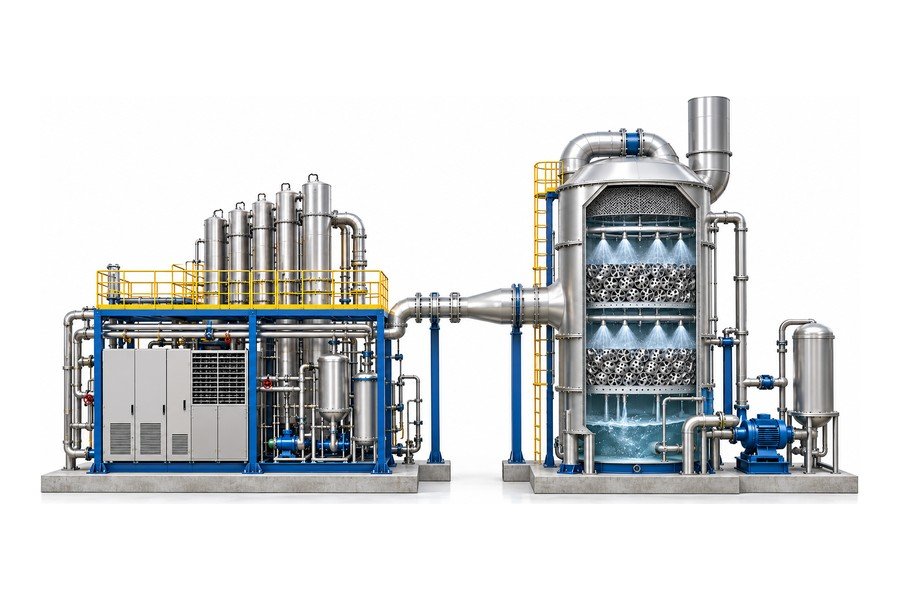
Source: Based on Micro-one in-house technical data · AI-assisted concept illustration · actual shapes and dimensions differ
04 · SELECTION CRITERIA
By what criteria, and in what order, should the options be chosen?
There are five criteria. An option that fails any one of them drops off the list.
- Space: Check whether there is room for a reactor or additional equipment, and a route to connect to existing piping and ducts. Without space, the options left are those that work within existing equipment.
- Capital cost: Look beyond the cost of new equipment and include the downtime and the scope of modification.
- Operating cost: Reagent, reheating fuel, ozone generation power, catalyst replacement and fan power from rising pressure drop make up the annual cost.
- Reheating: The more the catalyst sits where gas temperature has dropped, as in tail-end SCR, the greater the reheating burden.
- Equipment compatibility: The method to be installed must accommodate the existing baghouse tubesheet and cage dimensions, loads and operating temperature range.
Run the checks in this order
Temperature comes first because temperature conditions decide the method itself. If the furnace has an SNCR temperature window, SNCR is a candidate; if the boiler outlet gas falls within the catalyst temperature range (roughly 250–430°C), high-dust SCR; if the baghouse operating temperature falls within the catalyst activity range, a catalytic filter; and if the train runs below 100°C with a wet scrubber, ozone oxidation. Tail-end SCR is considered on the assumption of reheating.[6] Looking at efficiency tables without knowing the temperature leads to comparing methods that do not fit.
Source: Based on Micro-one in-house technical data · concept summary
Yes. A typical setup uses SNCR to lower the average and a downstream stage to catch the fluctuations. Because each method uses reagent, however, the combined slip and reagent consumption must be managed together.
05 · FIBER-TYPE CATALYTIC FILTER
Where can a fiber-type catalytic filter be considered?
A catalytic filter bag is a filter bag made from catalyst-loaded filter media: it filters out dust and reduces NOx on the catalyst. Where an existing baghouse is in service and the tubesheet and cage dimensions match, DeNOx capability can be added within the scope of replacing the filter bags and adding a reagent injection system. Compared with methods that require new equipment or a reactor, the smaller burden on space and modification scope is the reason to consider this approach.
The conditions to check beforehand are equally clear. First, the operating temperature must fall within the catalyst activity range. Second, the baghouse tubesheet and cage dimensions must match the new filter bags. Third, there must be a location for reagent injection with enough mixing distance. Fourth, if the gas carries many poisoning components, catalyst life must be assessed separately. If all of these conditions are met, the option goes on the list; if any one fails, compare it with the other options in the previous section.
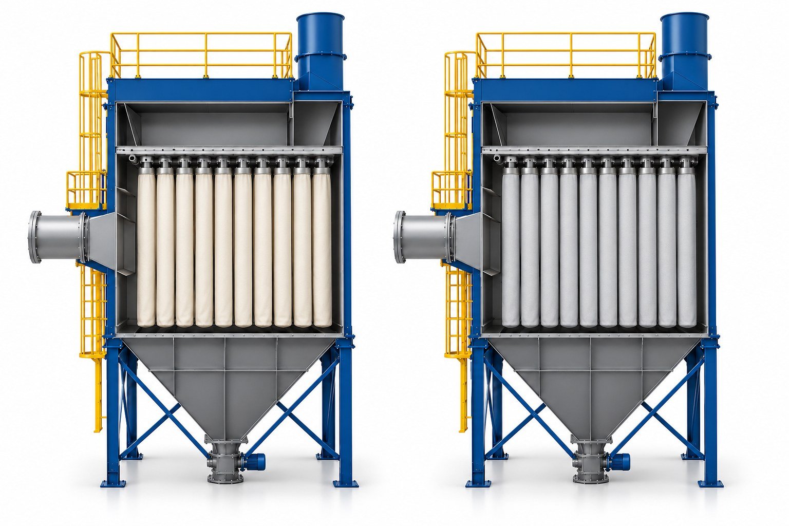
Figure 3. A baghouse with conventional filter bags (left) compared with one fitted with a reagent injection system and catalytic filter bags (right) (concept illustration)
Left: a baghouse with conventional filter bags (cream). Right: the same baghouse with a reagent injection system added and the bags replaced with catalytic filter bags (light gray).
Source: Based on Micro-one in-house technical data · AI-assisted concept illustration · actual shapes and dimensions differ
Only a handful of catalytic filter bag suppliers, such as Gore, Topsoe and Micro-one, have delivered to customer sites and built up an operating track record in this field. In 2024, Micro-one delivered 3,300 CataFill™ catalytic filter bags to the Kanding incinerator in Taiwan. Whatever the product, whether it suits site conditions needs case-by-case review.
FAQ
Frequently asked questions
When emission limits get stricter, is upgrading the existing SNCR enough?
It can be, depending on the site. If the required reduction is small and more injection points can be placed within the in-furnace temperature window, an SNCR upgrade may be sufficient. If the required reduction is large or the temperature fluctuates widely, rising slip sets a limit, so downstream polishing should be considered as well.
How long a shutdown is needed to add DeNOx equipment to an operating incinerator?
It depends on the method and the scope of modification. Methods that add a new reactor need duct connections and foundation work, which lengthens the shutdown, while methods limited to replacing filter bags can sometimes be fitted into a scheduled maintenance outage. The exact duration is set after a site survey.
Do catalytic filters cost less to operate than tail-end SCR?
It depends on conditions. In tail-end SCR, reheating energy is a large share of operating cost, whereas catalytic filters react within the filtration system and in some cases need no separate reheating. Filter bag replacement intervals and reagent cost, however, must be compared as well.
Can ozone oxidation be applied to any incinerator?
No. The flue gas must be below 100°C, and a scrubber must be in place to absorb the soluble NOx produced by ozone oxidation. Without these conditions, the reduction of up to 80–95% cannot be expected either.
- Ministry of Environment, Korea, "Press release on the amendment of the Enforcement Rule of the Clean Air Conservation Act", Korea.kr Policy Briefing (in Korean). Policy Briefing press release
- "Special Act on the Improvement of Air Quality in Air Control Zones" (Articles 17 and 19), Korea Law Information Center, Ministry of Government Legislation (in Korean). Air Control Zones Act
- "Act on the Integrated Control of Pollutant-Discharging Facilities" (Articles 8 and 9), Korea Law Information Center, Ministry of Government Legislation (in Korean). Integrated Control Act
- Korea Environment Corporation, "CleanSYS Glossary" (30-minute average data) (in Korean). CleanSYS Glossary
- U.S. EPA, "Air Pollution Control Cost Manual, Section 4 Chapter 1: Selective Noncatalytic Reduction", 2016. EPA SNCR Cost Manual
- U.S. EPA, "Air Pollution Control Technology Fact Sheet: Selective Catalytic Reduction (SCR)". EPA SCR Fact Sheet
- GEA, "BisCat catalytic ceramic candle filter". GEA BisCat
- Topsoe, "CataFlex™". Topsoe CataFlex
- Gore, "GORE® DeNOx Catalytic Filter Bags". Gore DeNOx catalytic filter bags
- Suchak, N. J., US Patent 9,440,188 B2, "Method for removing contaminants from exhaust gases". US 9440188 B2
- Ministry of Government Legislation, Easy-to-Find Practical Legal Information, "Exemption of total-load management operators from emission charges" (related to Article 19 of the Air Control Zones Act) (in Korean). Easy-to-Find Practical Legal Information
- Tri-Mer, "Ceramic Filter Systems" (operating temperature of catalytic ceramic filters). Tri-Mer Ceramic Filter Systems